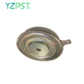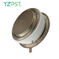

Wysokie dV / dt Typ urządzenia tyrystorowego z zamontowanym ciśnieniem
Pobierz najnowszą cenę| Rodzaj płatności: | L/C,T/T,Paypal |
| Incoterm: | FOB,CFR,CIF |
| transport: | Ocean,Air |
| Porta: | Shanghai |

| Rodzaj płatności: | L/C,T/T,Paypal |
| Incoterm: | FOB,CFR,CIF |
| transport: | Ocean,Air |
| Porta: | Shanghai |
Model No: YZPST-KK2500A2500V
Marka: YZPST
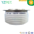
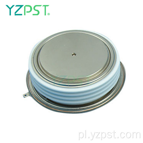
TARNIK WYSOKIEJ MOCY
YZPST-KK2500A2500V
TARRISTY O WYSOKIEJ MOCY DO APLIKACJI KONTROLI FAZ
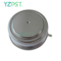
Cechy: . Wszystkie rozproszone struktury . Interdigitated Amplifying Gate Configuration . Gwarantowany maksymalny czas wyłączenia
. Wysoka zdolność dV / dt . Urządzenie zmontowane ciśnieniowo
|
Parameter |
Symbol |
Min. |
Max. |
Typ. |
Units |
Conditions |
|
Average value of on-state current |
IT(AV) |
|
2500 |
|
A |
Sinewave,180o conduction,Tc=70oC |
|
RMS value of on-state current |
ITRMS |
|
3900 |
|
A |
Nominal value |
|
Peak one cPSTCle surge (non repetitive) current |
ITSM |
|
45000
42000 |
|
A
A |
8.3 msec (60Hz), sinusoidal wave- shape, 180o conduction, Tj = 125 oC 10.0 msec (50Hz), sinusoidal wave- shape, 180o conduction, Tj = 125 oC |
|
I square t |
I2t |
|
5.5x10⁶ |
|
A2s |
8.3 msec |
|
Latching current |
IL |
|
1000 |
|
mA |
VD = 24 V; RL= 12 ohms |
|
Holding current |
IH |
|
500 |
|
mA |
VD = 24 V; I = 2.5 A |
|
Peak on-state voltage |
VTM |
|
2.00 |
|
V |
ITM = 3000 A; Tj = 125 oC |
|
Critical rate of rise of on-state current (5, 6) |
di/dt |
|
800 |
|
A/ms |
Switching from VDRM£ 1000 V, non-repetitive |
|
Critical rate of rise of on-state current (6) |
di/dt |
|
300 |
|
A/ms |
Switching from VDRM£ 1000 V |

Bramkowanie
|
Parameter |
Symbol |
Min. |
Max. |
Typ. |
Units |
Conditions |
|
Peak gate power dissipation |
PGM |
|
200 |
|
W |
tp = 40 us |
|
Average gate power dissipation |
PG(AV) |
|
5 |
|
W |
|
|
Peak gate current |
IGM |
|
20 |
|
A |
|
|
Gate current required to trigger all units |
IGT |
|
300 200 125 |
|
mA mA mA |
VD = 6 V;RL = 3 ohms;Tj = -40 oC VD = 6 V;RL = 3 ohms;Tj = +25 oC VD = 6 V;RL = 3 ohms;Tj = +125oC |
|
Gate voltage required to trigger all units
|
VGT |
0.30 |
5 4
|
|
V V V |
VD = 6 V;RL = 3 ohms;Tj = -40 oC VD = 6 V;RL = 3 ohms;Tj = 0-125oC VD = Rated VDRM; RL = 1000 ohms; Tj = + 125 oC |
|
Peak negative voltage |
VGRM |
|
20 |
|
V |
|
Dynamiczny
|
Parameter |
Symbol |
Min. |
Max. |
Typ. |
Units |
Conditions |
|
Delay time |
td |
|
2.0 |
|
ms |
ITM = 50 A; VD = 67% VDRM Gate pulse: VG = 30 V; RG = 10 ohms; tr = 0.1 ms; tp = 20 ms |
|
Turn-off time (with VR = -5 V) |
tq |
|
80
|
|
ms |
ITM > 2000 A; di/dt = 25 A/ms; VR³ -5 V; Re-applied dV/dt = 400 V/ms linear to 67% VDRM ; Tj = 125 oC; Duty cPSTCle ³ 0.01% |
|
Reverse recovery current |
Irr |
|
200 |
|
A |
ITM > 2000 A; di/dt = 25 A/ms; VR³ -50 V; Tj = 125 oC |
CHARAKTERYSTYKA TERMICZNA I MECHANICZNA I OZNACZENIA
|
Parameter |
Symbol |
Min. |
Max. |
Typ. |
Units |
Conditions |
|
Operating temperature |
Tj |
-40 |
+125 |
|
oC |
|
|
Storage temperature |
Tstg |
-40 |
+150 |
|
oC |
|
|
Thermal resistance - junction to case |
RQ (j-c) |
|
0.012
|
|
oC/W |
Double sided cooled Single sided cooled |
|
Thermal resistamce - case to sink |
RQ (c-s) |
|
0.002
|
|
oC/W |
Double sided cooled * Single sided cooled * |
|
Mounting force |
P |
8000 35.5 |
10000 44.4 |
|
lb. kN |
|
|
Weight |
W |
|
|
3.5 1.60 |
Lb. Kg. |
|
* Powierzchnie montażowe są gładkie, płaskie i nasmarowane
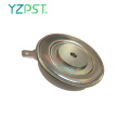
Uwaga: w przypadku obrysu i wymiarów obudowy, patrz rysunek szkicu obudowy na stronie 3 niniejszej dokumentacji technicznej

A: 73 mm
B: 109 mm
C: 98 mm
E: 36 mm


Tel: 86-514-87782298
Whatsapp: +8613805278321
Adres: 3rd Floor, Weiheng Building No.20 B Area, Yangzhou, Jiangsu China
Witryna internetowa: https://pl.yzpst.com


Privacy statement: Your privacy is very important to Us. Our company promises not to disclose your personal information to any external company with out your explicit permission.
Fill in more information so that we can get in touch with you faster
Privacy statement: Your privacy is very important to Us. Our company promises not to disclose your personal information to any external company with out your explicit permission.