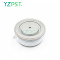


Tyrystor dużej mocy do zastosowań w falownikach
$801-199 Piece/Pieces
$40≥200Piece/Pieces
| Rodzaj płatności: | L/C,T/T,Paypal |
| Incoterm: | FOB,CFR,CIF |
| Min. Zamówienie: | 1 Piece/Pieces |
| transport: | Ocean,Air |
| Porta: | Shanghai |

$801-199 Piece/Pieces
$40≥200Piece/Pieces
| Rodzaj płatności: | L/C,T/T,Paypal |
| Incoterm: | FOB,CFR,CIF |
| Min. Zamówienie: | 1 Piece/Pieces |
| transport: | Ocean,Air |
| Porta: | Shanghai |
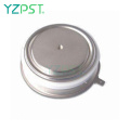
Model No: YZPST-R0929LC10 (TQ<10US)
Marka: YZPST

TYRYSTOR O WYSOKIEJ MOCY DO ZASTOSOWAŃ FALOWNIKA
YZPST-R0929LC10 (TQ <10US)
Funkcje tyrystora:
. Wszystkie rozproszone struktury
. Konfiguracja Interdigitated Amplifying Gate
. Gwarantowany maksymalny czas wyłączenia
. Wysoka zdolność dV / dt
. Urządzenie montowane pod ciśnieniem
CHARAKTERYSTYKA ELEKTRYCZNA I OCENY
Blokowanie - stan wyłączony
|
VRRM (1) |
VDRM (1) |
VRSM (1) |
|
1000 |
1100 |
1200 |
V RRM = powtarzalne szczytowe napięcie wsteczne
V DRM = powtarzalne napięcie szczytowe wyłączone
V RSM = nie powtarzalne szczytowe napięcie wsteczne (2)
Uwagi:
Wszystkie oceny podano dla Tj = 25 o C, chyba że zaznaczono inaczej.
(1) Wszystkie wartości napięcia są określone dla zastosowanego
Sinusoidalny kształt fali 50 Hz / 60 Hz w
zakres temperatur od -40 do +125 o C.
(2) 10 ms. max. szerokość impulsu
(3) Maksymalna wartość dla Tj = 125 o C.
(4) Minimalna wartość kształtu fali liniowej i wykładniczej do 80% znamionowego V DRM . Otwarcie bramy. Tj = 125 o C.
(5) Wartość niepowtarzalna.
(6) Wartość di / dt ustala się zgodnie ze standardem EIA / NIMA RS-397, sekcja 5-2-2-6. Zdefiniowana wartość byłaby dodatkowa do wartości uzyskanej z obwodu ubbera, zawierającego kondensator 0,2 mF i rezystancję 20 omów równolegle z testowanym tristorem.
|
Repetitive peak reverse leakage and off state leakage |
IRRM / IDRM |
15 mA 70 mA (3) |
|
Critical rate of voltage rise |
dV/dt (4) |
200 V/msec |
Prowadzenie - stan włączony
|
Parameter |
Symbol |
Min. |
Max. |
Typ. |
Units |
Conditions |
|
Max. average value of on-state current |
IT(AV)M |
|
929 |
|
A |
Sinewave,180o conduction,Tc=55oC |
|
RMS value of on-state current |
IT(RMS)m |
|
1893 |
|
A |
Nominal value |
|
Peak one cPSTCle surge (non repetitive) current |
ITSM |
|
-
9.0 |
|
kA
kA |
8.3 msec (60Hz), sinusoidal wave- shape, 180o conduction, Tj = 125 oC 10.0 msec (50Hz), sinusoidal wave- shape, 180o conduction, Tj = 125 oC |
|
I square t |
I2t |
|
405x103 |
|
A2s |
8.3 msec |
|
Latching current |
IL |
|
- |
|
mA |
VD = 24 V; RL= 12 ohms |
|
Holding current |
IH |
|
1000 |
|
mA |
VD = 24 V; I = 2.5 A |
|
Peak on-state voltage |
VTM |
|
2.04 |
|
V |
ITM = 1400 A |
|
Critical rate of rise of on-state current (5, 6) |
di/dt |
|
1500 |
|
A/ms |
Switching from VDRM £ 1000 V, non-repetitive |
|
Critical rate of rise of on-state current (6) |
di/dt |
|
1000 |
|
A/ms |
Switching from VDRM £ 1000 V |
Bramkowanie
|
Parameter |
Symbol |
Min. |
Max. |
Typ. |
Units |
Conditions |
|
Peak gate power dissipation |
PGM |
|
30 |
|
W |
|
|
Average gate power dissipation |
PG(AV) |
|
2 |
|
W |
|
|
Peak gate current |
IGM |
|
- |
|
A |
|
|
Gate current required to trigger all units |
IGT |
|
300 |
|
mA |
VD = 10 V;IT=3A;Tj = +25 oC
|
|
Gate voltage required to trigger all units
|
VGT |
|
3.0 |
|
V
|
VD = 10 V;IT=3A;Tj = +25 oC
|
|
Peak negative voltage |
VRGM |
|
5 |
|
V |
|
Dynamiczny
|
Parameter |
Symbol |
Min. |
Max. |
Typ. |
Units |
Conditions |
|
Delay time |
tgd |
|
1.0 |
- |
ms |
VD=67% VDRM, IT=2000A, di/dt=60A/us, IFG=2A, tr=0.5us, Tj=25C |
|
Turn-on time |
tgt |
|
2.0 |
- |
|
|
|
Turn-off time (with VR = -5 V) |
tq |
- |
10 |
- |
ms |
ITM=1000A, tp=1000us, di/dt=60A/us, Vr=50V, Vdr=33%VDRM, dVdr/dt=200V/us |
|
Reverse recovery current |
Irm |
|
- |
|
A |
ITM=4000A, tp=2000us, di/dt=60A/us |
CECHY TERMICZNE I MECHANICZNE I OCENY
|
Parameter |
Symbol |
Min. |
Max. |
Typ. |
Units |
Conditions |
|
Operating temperature |
Tj |
-40 |
+125 |
|
oC |
|
|
Storage temperature |
Tstg |
-40 |
+150 |
|
oC |
|
|
Thermal resistance - junction to case |
RQ (j-c) |
|
- - |
|
K/kW |
Double sided cooled Single sided cooled |
|
Thermal resistamce - case to sink |
RQ (c-s) |
|
- - |
|
K/kW |
Double sided cooled * Single sided cooled * |
|
Thermal resistance - junction to case |
RQ (j-s) |
|
32 64 |
|
K/kW |
Double sided cooled Single sided cooled |
|
Mounting force |
F |
10 |
20 |
- |
kN |
|
|
Weight |
W |
|
|
- |
Kg |
about |


Tel: 86-514-87782298
Whatsapp: +8613805278321
Adres: 3rd Floor, Weiheng Building No.20 B Area, Yangzhou, Jiangsu China
Witryna internetowa: https://pl.yzpst.com


Privacy statement: Your privacy is very important to Us. Our company promises not to disclose your personal information to any external company with out your explicit permission.
Fill in more information so that we can get in touch with you faster
Privacy statement: Your privacy is very important to Us. Our company promises not to disclose your personal information to any external company with out your explicit permission.