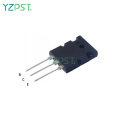

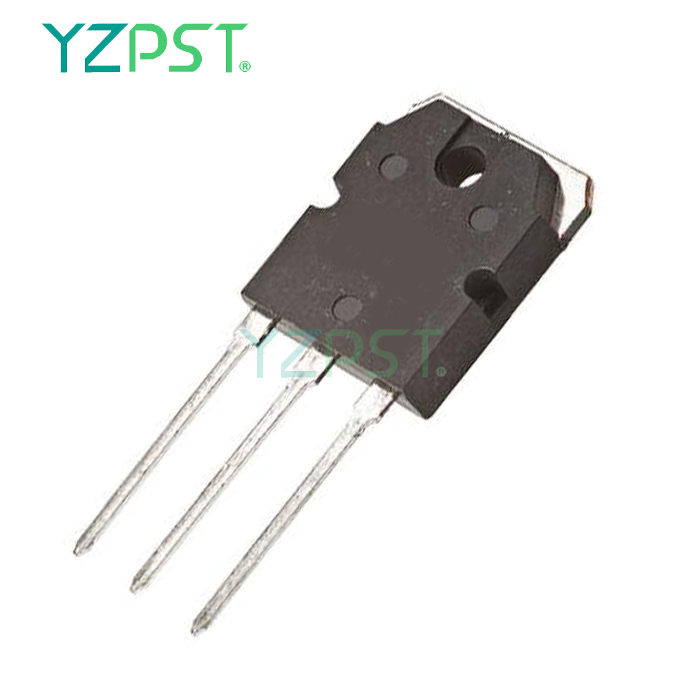
TO-247 Konwerter DC-AC Komplementarne tranzystory NPN
Pobierz najnowszą cenę| Rodzaj płatności: | L/C,T/T,Paypal |
| Incoterm: | FOB,CFR,CIF |
| transport: | Ocean,Air |
| Porta: | Shanghai |

| Rodzaj płatności: | L/C,T/T,Paypal |
| Incoterm: | FOB,CFR,CIF |
| transport: | Ocean,Air |
| Porta: | Shanghai |
Model No: YZPST-2SDW100
Marka: YZPST
Komplementarne tranzystory Darlington
YZPST-2SDW100
cechy
■ Uzupełniające tranzystory NPN - PNP
■ Monolityczna konfiguracja Darlington
Aplikacje
■ Wzmacniacz mocy audio
■ Konwerter DC-AC
■ Niskonapięciowy silnik prądu stałego
■ Aplikacje do przełączania ogólnego przeznaczenia
Opis
Urządzenia są produkowane w technologii planarnej z układem [base island] i monolityczną konfiguracją Darlington.
T a b le 1 . D e v i c e s ummary
|
Order code |
Marking |
Package |
Packaging |
|
2SDW100 |
2SDW100 |
TO-247 |
Tube |
|
2SDW200 |
2SDW200 |
1 Bezwzględny maxi m un oceny
T a b le 2 . Ab s o l ut e m a x i m u m ra ti ngs
|
Symbol |
Parameter |
Value |
Unit |
|
|
NPN |
2SDW100 |
|||
|
PNP |
2SDW200 |
|||
|
VCBO |
Collector-emitter voltage (IE = 0) |
80 |
V |
|
|
VCEO |
Collector-emitter voltage (IB = 0) |
80 |
V |
|
|
IC |
Collector current |
25 |
A |
|
|
ICM |
Collector peak current (tP < 5 ms) |
40 |
A |
|
|
IB |
Base current |
6 |
A |
|
|
IBM |
Base peak current (tP < 5 ms) |
10 |
A |
|
|
PTOT |
Total dissipation at Tc ≤ 25 °C |
130 |
W |
|
|
TSTG |
Storage temperature |
-65 to 150 |
°C |
|
|
TJ |
Max. operating junction temperature |
150 |
°C |
|
Nie t e : F lub PN P ty p e v ol t a ge a nd k u r r e NT v al u e s a r e n e g a ti v e
T a b le 3 . T herm al d ta
|
Symbol |
Parameter |
Value |
Unit |
|
RthJC |
Thermal resistance junction-case max |
0.96 |
°C/W |
2 Elektryczne c h cechy
T ca s e = 2 5 ° C; chyba że inne w Ise spe c ified.
|
|
Symbol |
Parameter |
Test conditions |
Min. |
Typ. |
Max. |
Unit |
|
ICBO |
Collector cut-off current (IE = 0) |
VCE = 80 V |
|
|
0.5 |
mA |
|
ICEV |
Collector cut-off current (VBE = - 0.3 V) |
VCE = 80 V |
|
|
0.1 |
mA |
|
ICEO |
Collector cut-off current (IB = 0) |
VCE = 60 V |
|
|
0.5 |
mA |
|
IEBO |
Emitter cut-off current (IC = 0) |
VEB = 5 V |
|
|
2 |
mA |
|
VCEO(sus) (1) |
Collector-emitter sustaining voltage (IB = 0) |
IC = 50 mA |
80 |
|
|
V |
|
VCE(sat)(1) |
Collector-emitter saturation voltage |
IC = 5 A IB = 20 mA IC = 10 A IB = 40 mA IC = 20 A IB = 80 mA |
|
|
1.2 1.75 3.5 |
V V V |
|
VBE(sat)(1) |
Base-emitter saturation voltage |
C B |
|
|
3.3 |
V |
|
(1) |
Base-emitter voltage |
I = 10 A V = 3 V |
1 |
|
3 |
V |
|
hFE(1) |
DC current gain |
IC = 5 A VCE = 3 V IC = 10 A VCE = 3 V IC = 20 A VCE = 3 V |
600 500 300 |
|
15000 12000 6000 |
|
|
VF(1) |
Diode forward voltage |
IF = 10 A |
|
TBD |
|
V |
|
Is/b |
Second breakdown current |
VCE = 25 V t = 500 ms |
|
TBD |
|
A |
1. Test impulsu: czas trwania impulsu ≤ 300 μs, cykl pracy ≤ 2%.
Dla typu PNP wartości napięcia i prądu są ujemne.
TO- 2 4 7 M e ch a ni c a l dane
|
Dim. |
mm. |
||
|
Min. |
Typ |
Max. |
|
|
A |
4.85 |
|
5.15 |
|
A1 |
2.20 |
|
2.60 |
|
b |
1.0 |
|
1.40 |
|
b1 |
2.0 |
|
2.40 |
|
b2 |
3.0 |
|
3.40 |
|
c |
0.40 |
|
0.80 |
|
D |
19.85 |
|
20.15 |
|
E |
15.45 |
|
15.75 |
|
e |
|
5.45 |
|
|
L |
14.20 |
|
14.80 |
|
L1 |
3.70 |
|
4.30 |
|
L2 |
|
18.50 |
|
|
øP |
3.55 |
|
3.65 |
|
øR |
4.50 |
|
5.50 |
|
S |
|
5.50 |
|


Tel: 86-514-87782298
Whatsapp: +8613805278321
Adres: 3rd Floor, Weiheng Building No.20 B Area, Yangzhou, Jiangsu China
Witryna internetowa: https://pl.yzpst.com


Privacy statement: Your privacy is very important to Us. Our company promises not to disclose your personal information to any external company with out your explicit permission.
Fill in more information so that we can get in touch with you faster
Privacy statement: Your privacy is very important to Us. Our company promises not to disclose your personal information to any external company with out your explicit permission.